
Optimizing Quill and Injector Performance in Refinery Operations
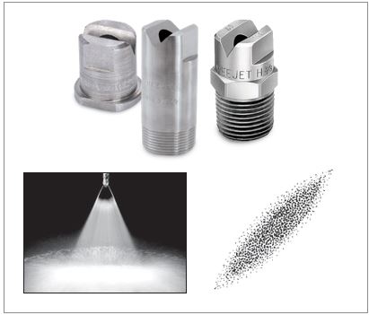
There are dozens of operations in refineries where quills and injectors are used. It is important to understand the differences between a quill and an injector. The terms are often used interchangeably even though the devices are quite different. An injector has one or more spray nozzles on a pipe and delivers a specific volume of fluid at a specified pressure drop. See Figure 1. The nozzle(s) convert fluid into a predictable drop size spectrum and provide specific spray characteristics. The use of spray nozzles allows more control over the distribution of the injected liquid into the receiving process fluid.
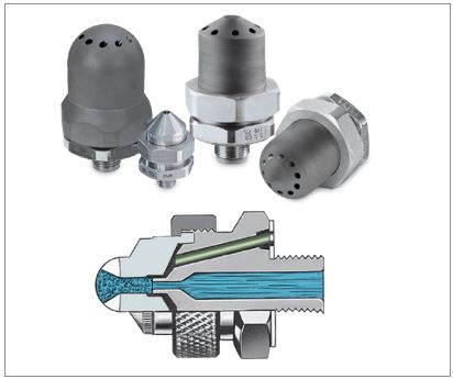
A quill is a pipe with slots or holes. See Figure 2. The injected fluid flow is uninhibited. The receiving process stream breaks up and mixes the injected fluid.
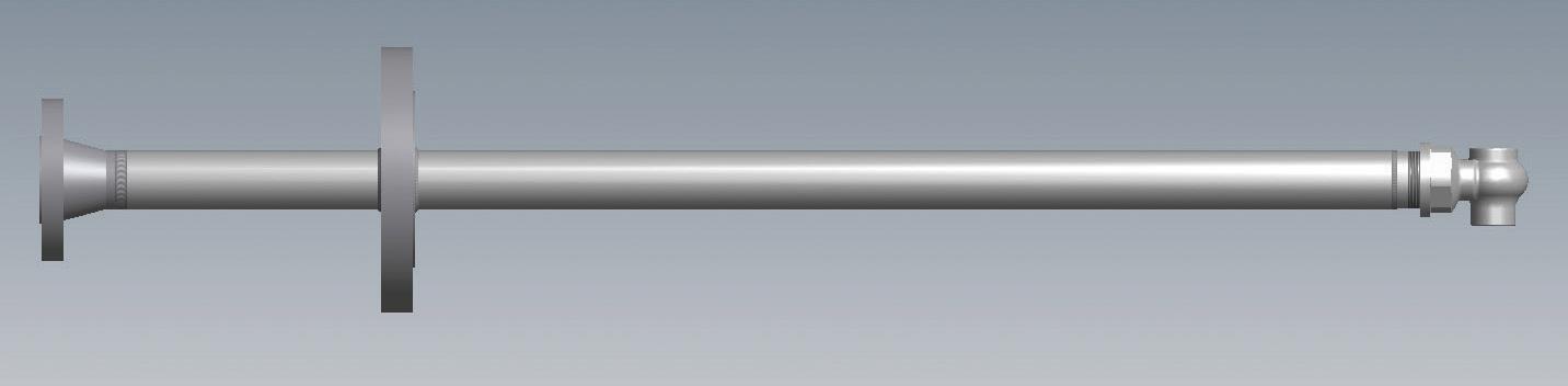
Figure 1: Injector with
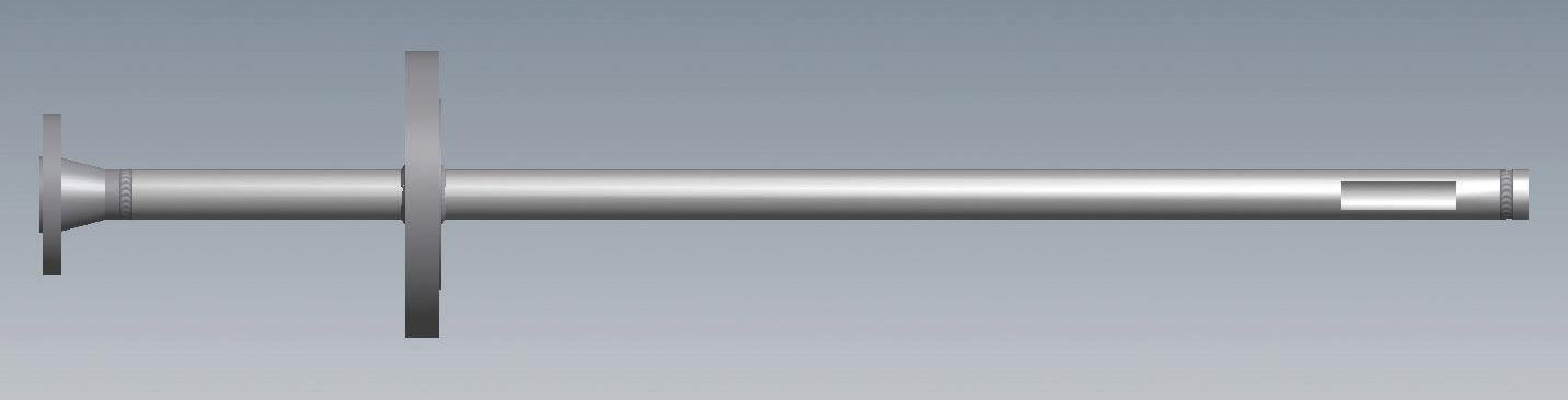
Figure 2: Quill
Should you use a quill or an injector?
The answer is somewhat dependent on your operation but, in general, you should use an injector unless you don’t need any control over spray characteristics such as flow rate, drop size or spray pattern.
The most common uses for quills and injectors are in gas conditioning, chemical injection and water wash. (See below for a complete list.) Here are a few examples that show the performance advantages of injectors over quills.
If you are cooling a gas, it is critical to know drop size since it is proportional to how fast the cooling will be achieved and when drop evaporation will occur. If droplets are too large, you may not achieve the desired cooling effect. This can result in excess fluid in the pipe or duct, cause maintenance problems and damage downstream equipment.
Chemical injection requires a greater surface area of injected liquid. Greater surface area requires better gas- to-liquid (or liquid-to-liquid) interaction to ensure efficient heat or mass transfer.
A third example is water wash. The wash water, via surface area contact, must have sufficient interaction with the vapor stream to dilute the corrosives and dissolve any water-soluble materials present. An injector with a spray nozzle provides more efficient mixing and better drop size breakup than a quill and can provide more control over the process – something a quill cannot achieve.
Injectors cost more than quills. However, given the long service life requirements of injectors and quills – up to 10 years – the cost differential between the two is insignificant should a problem occur due to imprecise flow. The cost of unscheduled downtime, damage to downstream equipment or incomplete cooling, washing or chemical reactions will greatly exceed the price differential between a quill and an injector.
What You Need to Know About Injector Spray Nozzles
Spray nozzles fall into two categories: hydraulic or air atomizing. A single liquid flows through a hydraulic nozzle. A liquid and a gas flow through air atomizing nozzles. Air atomizing nozzles are often called dual fluid nozzles.
Spray nozzles are designed to produce a spray pattern: full cone, hollow cone or flat spray.
FULL CONE SPRAYS are formed by swirling the fluid inside the nozzle by a stationary vane. There is a distribution of small to larger size droplets throughout the pattern. Among hydraulic spray nozzles, full cone nozzles produce the largest droplets for a given flow rate and pressure.
The maximum free passage in full cone nozzles is a bit limited due to the vane design, so it is important to keep in mind that clogging could be a problem when using liquids with suspended particulates. If there are particulates in the fluid, consider using full cone spray nozzles featuring a maximum free passage design.
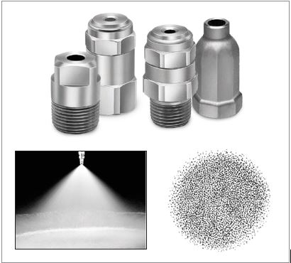
Typical uses: overhead water wash, defoaming, torch oil injectors
HOLLOW CONE SPRAYS are formed by injecting a stream of fluid tangentially into a swirling chamber. The swirling action allows a uniform film of liquid to discharge from the nozzle forming a ring of fluid. Hollow cone spray nozzles produce smaller droplets and a tighter spectrum of droplets than
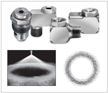
Typical uses: flue gas cooling and urea injection for SNCR NOx control, desuperheating, quenching and water wash.
FLAT SPRAY NOZZLES use an elliptical orifice to create a flat fan spray pattern. The exact shape of the orifice determines the spray angle which can range from a solid stream to a 120° spray angle. Drop size is medium smaller than full cone sprays and larger than hollow cone sprays.
Typical uses: steam quench, desuperheating, torch oil injectors and catalyst reforming cooling.
AIR ATOMIZING NOZZLES are available in a wide range of spray patterns – hollow cone, full cone
The liquid and gas streams in dual fluid nozzles are typically kept separate until the two fluids are brought together just behind the discharge orifice. This enables mixing efficiency to be maximized and the smallest possible drop to be produced. If the two fluids are mixed earlier, coalescence and drag would increase drop size.
Air atomizing spray nozzles designed for operation at low flow rates – 2 to 5
Typical uses: gas cooling, fresh feed injectors to FCC units, emergency quench and urea injection for NOx
One more selection consideration is the environment where the nozzle will spray. For nozzles to atomize, they need to spray into vapor – which is air or any other gas inside a duct system. Atomization does not occur when liquids are sprayed into liquids. When liquids are sprayed into liquids, the nozzle is acting more like a dispenser. Spray nozzles with multiple orifices may prove advantageous. Breaking the flow into multiple injection points can increase the mixing of the injected liquid with the process stream if it is also liquid.
Determining Spray Direction
There are two ways to spray: co-current or counter-current. Each approach has advantages and disadvantages. Table 1 summarizes the pros and cons of each approach.
There is no right or wrong answer on spray direction. The best direction is the one that will deliver the performance you need.
A common rule of thumb is to center the injector in the process pipe and spray co-currently. However, this doesn’t always produce the best results. See Table 2. This example illustrates how the type of spray nozzle used and the orientation of it can affect performance.
When the first and second spray nozzles in the chart below are compared, the impact of using a properly sized spray nozzle becomes clear. Wall wetting is decreased, the amount of water evaporated is increased and droplet size is smaller at the end of the pipe.
The third spray nozzle in Table 2 is the same as the second nozzle but it is spraying counter-current to the vapor stream. There is a slight increase in water contact with the wall as the spray plume opens up. However, a greater amount of water evaporation occurs, and droplet size is even smaller at the end of the pipe.
Which is the better spray direction? In this case, the application requirements will determine if 2% water contact with the wall is acceptable to achieve greater evaporation and cooling.
The placement of an injector in a pipe can significantly impact performance.
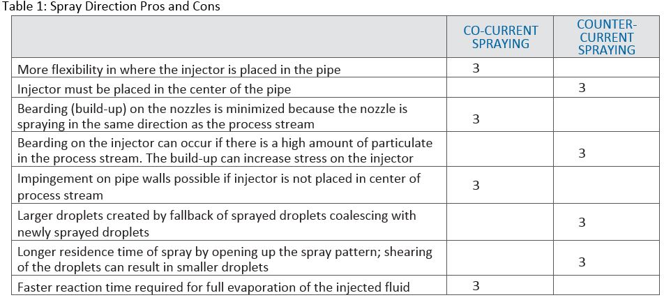
Table 1: Spray Direction Pros and Cons
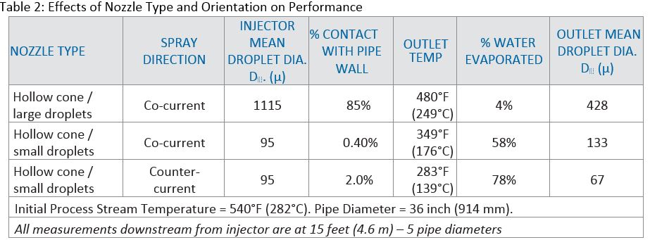
Table 2: Effects of Nozzle Type and Orientation on Performance
Injector Design Considerations
In addition to evaluating the factors that affect spray performance, injector design and construction must be carefully planned and validated. Operating conditions and service life will dictate design, materials of construction and the level of validation required. Pressure, temperature, corrosion
The operating environment typically determines the level of testing and construction validation required. Testing and documentation generally include many of the following:
- Weld qualifications/procedures and weld maps
- Positive Material Identification (PMI)
- Non-Destructive Examination (NDE)
- Radiographic Examination (RT)
- Liquid Penetrant Examination (PT)
- Visual Testing (VT)
- Ultrasonic Examination (UT)
- Material Traceability (MTR)
- Hydrostatic Testing (LT)
- Ferrite testing of welds
Using computer modeling to validate injector design and performance is generally recommended. Relying on theoretical calculations alone can be risky. Computer modeling is used for two purposes. The first,
For example, the velocity of the process stream can cause vortex shedding and premature injector failure. The length of the injector, the size of the pipe used for injector construction and the type of welds are all important considerations. Equally important are the types of forces on the injector in the process stream. A failure inside the process pipe is dangerous and costlier than using computer modeling to validate the system design before it is finalized and installed.
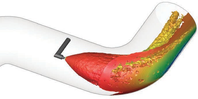
The second way modeling is used is to validate injector performance with Computational Fluid Dynamics (CFD) models. These models predict the interaction of the injected fluids with other fluids or a vapor and determine the heat transfer, mass transfer, chemical reactions and other flow related phenomena that will occur when the fluids interact under specific conditions. Unforeseen interactions can be identified, and design modifications can be made before injector construction begins.

Minimizing Maintenance Downtime
Injectors may need to be removed for inspection, routine maintenance or insertion in another location. Safely retracting the injector so an isolation valve can be closed prior to unbolting the injector from the process pipe is a major advantage.
There are two types of retractable injectors. One is removed manually and the other features a handwheel and screw mechanism that provides a mechanical assist. The mechanical retractable version provides an additional safety level since the injector cannot be retracted any faster than the handwheel operator allows. With the use of retractable injectors, the primary injector can be serviced safely offline and redundant injectors can be used to prevent process disruption.
Using retractable injectors can also help dramatically reduce downtime. One refinery in the midwestern U.S. is using mechanical retractable injectors to spray liquid nitrogen into the hydrocracker reactor to cool the catalyst prior to replacement. The injectors are inserted, and the cooling process begins while the plant is online. Previously, a partial shutdown of the refinery was required before the liquid nitrogen cooling process could begin. The shorter turnaround resulting from the use of the retractable injectors saves the refinery an estimated $2,000,000 by reducing downtime by two days.
Summary
The guidelines outlined here provide a good starting point when a new or replacement injector is required. However, the specifics of your operation will determine what’s necessary to optimize performance. You may find the following checklist helpful as you move forward with your next injector project.
- Don’t automatically replace like with Just because performance is OK doesn’t mean it can’t be better. You may be able to reduce wetting, decrease maintenance time, extend service life and more by revisiting the current design.
- Be meticulous about the details and eliminate open issues. Use modeling to uncover potential problems and ensure performance. Fixing problems after an injector is installed will cost considerably more than the investment in modeling.
- Consult with experts even if you are confident in your specifications and design. They have specialized equipment, modeling programs
and experience that can help validate your design. They may also recommend design enhancements based on advancements in spray technology.
Author
Chuck Munro has more than 20 years of experience with Spraying Systems Co. in spray nozzle and injector application assistance and troubleshooting. His areas of focus include water wash, emergency quench
HASTELLOY® is a registered trademark of Haynes International, Inc.
INCONEL® is a registered trademark of Special Metals Corporation group of companies


Comments