
Online Exclusive: API 610 12th Edition addresses pump reliability, maintainability and more
API 610 12th Edition addresses pump reliability, maintainability and more
Korkowski, Applied K3nowledge Consulting, Brea, California; T. Hess, E²G | The Equity Engineering Group, Inc., Shaker Heights, Ohio; and R. Jones, Consultant, Houston, Texas
Whenever a new edition of global specifications [e.g., International Organization for Standardization (ISO) and the American Petroleum Institute (API)] is released, there is usually massive confusion surrounding understanding explicit details of the key changes and why they were made. This article addresses five areas of changes that deal directly with pump reliability and maintainability, along with highlighting other various changes incorporated in API Standard 610 12th Edition, Centrifugal Pumps for Petroleum, Petrochemical and Natural Gas Industries, published in January 2021.
Background. API documents are typically updated on a 5-yr interval. API 610 12th Edition had a release date of January 2021, close to 11 yr after the published 11th Edition, primarily due to key items which required some additional time to resolve. The API 610 taskforce began working on this update in 2006. The group addressed the latest developments for rotating equipment, reliability issues, industry issues and proposed changes based upon proven, sound engineering and operating practices. Collaboration with other industry groups such as the Hydraulic Institute, the International Electrotechnical Commission (IEC), the National Electrical Manufacturers Association (NEMA) and ASTM ensured that this document reflected their latest updates. It should be noted that the API 610 12th Edition standard is no longer co-branded with ISO. The 9th, 10th and 11th Editions of API 610 were co-branded as ISO 13709.
The time required for the pump manufacturing industry to incorporate the changes to API 610 in the 12th Edition into their pump designs is difficult to determine. Historically, previous editions of API 610 have transitioned into worldwide usage over about a 2-yr period. Engineers generally will embrace certain changes to API 610 12th Edition because of the benefits presented by these changes, especially regarding the impact on pump reliability. The rest of this article highlights key changes in the standard, with some background explanations.
Significant changes. Key items in the 12th Edition addressing product reliability and maintainability are:
- New: Special Purpose Pumps (Annex O)
- New: Introduction of API RP 691 Risk Based Machinery Management
- Update: Basic Design Items—service life; 3-yr uninterrupted operation; hydraulic selection requirements; data sheets
- Update: Bearing Selection Criteria—energy density update for pipeline pumps; bearing oil and housing temperatures
- Update: Unit Packaging—“shaft” guards; baseplate designs for OH pumps and location of their auxiliaries; pipe gusseting.
Special purpose (high-energy) pumps—Annex O. In the 11th Edition, “high energy” was defined as pumps with heads per stage greater than 200 m (650 ft) and power per stage greater than 225 kW (300 hp). Only a stipulation for percentage of radial clearances between the diffuser vane or casing cut-water and the impeller blade in relation to their radii was addressed in the 11th Edition.
The sub-committee realized two things. First, “high energy” meant different things to different people, as evidenced by customers who have already written into their specifications what they consider high energy. Second, irrespective of “the definition” of high energy, the prescription of what exactly should be addressed for any high-energy pump was the more important issue. The decision was made to:
- Re-label these pumps as “special purpose”
- Add a “new” annex specifically dedicated to these pumps
- Annex to be “informative” instead of “normative”
The annex contains sections for definition; selection criteria for pressure boundary and rotor; design considerations for pressure boundary components, impellers, diffusers or volutes, shaft seals, bearings and bearing housings; materials; manufacturing; and testing guidelines. Product reliability and maintainability is critical for these high-energy pumps. Examples of special purpose pumps are:
- Single-stage, 5,490-rpm high-speed hydrogen and oxygen F-1 turbopumps used for the Saturn V booster rocket engines.
- 500-bar (7,500 psi) high-pressure, 6,000-rpm high-speed, 500-m (1,600 ft) per stage water injection pumps.
- High-pressure ethylene pipeline pumps.
- High-pressure boiler feed water pumps.
- Unspared 3 MW–4 MW (4,000 HP–5,400 HP) refinery charge pumps.
It is recognized that special purpose pumps constitute only about 1% of the entire pump population; however, they represent some of the greatest challenges for pump designers and need special design considerations. FIG. 1 represents one approach in defining pump energy level in terms of specific speed and total pressure rise per stage.
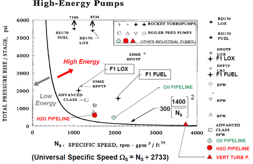
FIG. 1. Example of high-energy pumps based on specific speed vs. total pressure rise per stage.
For high-energy pumps, every aspect of the design requires careful review, including rotor stiffness, distribution of residual stresses in metal-to-metal sealing surfaces, determination of deflection at critical fits and the establishment of proper running clearances. Performing structural analysis of impellers and diffusers (or volutes) is essential as is determining the proper net positive suction head (NPSH) margin based upon incipient NPSH (NPSHi), not just the generic 3% NPSH3. Especially for new designs, finite element analysis (FEA) of the bearing housing should be done to carefully determine the types of bearings to use. Lastly, the ability to easily assemble and disassemble impellers must be taken into consideration. As for manufacturing requirements, patterns and rigging should provide sound castings while non-destructive testing of highly stressed areas should be performed.
Introduction of API RP 691 Risk Based Machinery Management. API 610 12th Edition now refers to API RP 691—Risk-based Machinery Management—by means of bulleted paragraphs whereby the purchaser needs to advise the vendor when this recommended practice document is invoked. API 691 defines technical readiness levels (TRL) for machinery, with TRLs ranging from conceptual, prototype equipment (TRL 0) to well established, field-proven machinery (TRL 7). When API RP 691 is invoked, the vendor is to advise the purchaser of the TRL of the equipment being offered. API 691 defines high-risk machinery as machinery that handles hazardous liquids or gases, services operating at temperatures of more than 177oC (350oF) and operating pressures of more than 80% of maximum allowable working pressure (MAWP), services operating at temperatures of more than 204oC (400oF), components with TRLs less than 7, liquid services operating at pressures higher than 41.4 bar (600 psig), and liquid services with specific gravity less than 0.5.
Basic design items. Several changes within the design section are covered here. These include the following:
- Removal of the 20-yr minimum service life, deleting 3-yr uninterrupted operation without shutting down equipment, hydraulic selection requirements and data sheets.
- API 610 11th Edition required a 20-yr minimum service life. This requirement was replaced in the 12th Edition with requiring only “field proven” equipment to be consistent with other API standards and with the API standard paragraphs. This eliminated any inferred equipment warranty issues.
- Three-year uninterrupted operation without shutting down equipment for vendor-specified maintenance or inspection was introduced in the 11th Edition and removed in the 12th This is easily achievable for pumps with either oil mist or force feed lubrication systems; however, for standard OH and BB pumps with standard lubrication methods, general yearly oil changes make compliance difficult as the pump should be shut down to change oil. The only way to comply would be to change oil on the fly, that is, while the pump is running, which is not recommended for safety reasons. Any uninterrupted operation requirement would need to be addressed in customer overlay or project specifications.
- Regarding hydraulic selection requirements, changes were made to address pump curve shape, parallel operation, NPSH datum point for vertically suspended pumps and data sheets.
- For several past API 610 editions, a continuous rising to shut-off head curve was mandatory for all pumps. The 12th Edition changed this to be a bullet item for customers to select when they want rising-to-shut-off head curves. However, a note in this bullet paragraph clearly states, “pumps with continuously rising head curve are preferred for all applications, but this is not possible with all pump types.” An example of this is low-specific speed pumps (typically low-flow/high-head, high speed pumps, which have slightly drooping curve shapes, and pumps with multiple radial blade (Barske) design impellers. For pumps operating in parallel, in addition to a minimum 10% rise-to-shut-off mandate, the 12th Edition requires pumps with discharge nozzles larger than 3 in. (80mm) within the preferred operating flow region, to have head values within 3% of each other. These stipulations ensure one pump will not “push” the second pump to shut-off.
- Regarding vertical suspended pumps, the NPSH3 (NPSH required) datum elevation point has changed from “top of foundation” to “impeller suction eye.” Similarly for vertical inline pumps, NPSH3 datum changed from “centerline of pump suction nozzle” to “eye of the impeller.” These changes establish consistency with horizontal pumps whose NPSH3 reference point is the shaft centerline. The same NPSH3 datum elevation criteria now applies to NPSHA (NPSH available) which is given by the customer.
- Important changes to the API 610 data sheets were made to address all alternate hydraulic operating points: rated and normal (same as before); however, now three additional operating points for customers to advise. These could be for handling a different liquid (as typically found with pipeline pumps or tank farms) or even liquids used to flush pumps during maintenance periods. Most important is that the driver (usually electric motor) is selected to handle the power requirements to handle all these operating conditions, which may have large differences in specific gravity causing an increase in Kw (Hp). Besides data sheets, the 12th Edition introduces a data list, which includes all data found on the data sheets; however, in a tabular form to compile all data into a neutral format to support electronic data exchange (EDE) among contractor, end user and pump manufacturer to minimize possible errors in transposing numbers among all parties.
Bearing selection criteria. Currently in the 11th Edition, hydrodynamic radial and thrust bearings are mandated when the energy density (i.e., pump rated power times the rated speed) is 4 x 10⁶ kW/min (5.4 x 10⁶ hp/min) or greater. For the 12th Edition, this requirement has slightly changed from applying to “all” to “most” services. The document specifically explains that for pipeline services, hydrodynamic radial and ball thrust bearing arrangement may be used instead of hydrodynamic radial and tilting pad thrust bearings based upon the pump manufacturer’s successful field experience when exceeding the above energy density limits. Reported experiences for higher energy density levels have been around 10.7 x 10⁶ kW/min (14.3 x 10⁶ hp/min).
Pipeline services are characteristic of pumping products with lower product temperatures vs. medium to hot temperature liquids found in refinery services. Because of this, API 610 12th Edition now states the limit for using sleeve/sleeve-ball bearings in pipeline pumps as 8 × 10⁶ kW/min (10.7 × 10⁶ hp/min) after which hydrodynamic radial and thrust bearings are to be used. The 12th Edition also states that for pipeline pumps, with energy density values between 4 × 10⁶ kW/min (5.4 × 10⁶ hp/min) and 8 × 10⁶ kW/min (10.7 × 10⁶ hp/min), hydrodynamic radial bearings shall be used with either rolling-element or hydrodynamic thrust bearings.
The hydrodynamic radial and thrust bearing arrangement requires a pressurized lubrication system. With the updated bearing selection criteria for pipeline pumps, pressurized lubrication systems are no longer required with use of hydrodynamic radial and ball thrust bearings. Pipeline pumps are typically in remote locations and not subject to frequent maintenance. Eliminating the pressurized lubrication system significantly reduces the maintenance and operator surveillance required for reliable pump operation. Regarding rolling-element type radial and thrust bearings, the 12th Edition now states that for oilfield and pipeline services, the specified limits may be exceeded basis vendor’s successful experience with customer’s approval.
Bearing temperature limits during shop testing for pressurized and ring-oiled or splash lubrication systems were changed in 12th Edition from the absolute temperature limits above a fixed ambient temperature of 43oC (110oF) in the 11th Edition to a more appropriate temperature rise. The oil temperature rise limits in the 12th Edition are 28K (50oF) for pressurized systems and 39K (70oF) for ring-oiled or splash system sump oil. A paragraph was added for a maximum allowable bearing housing surface temperature of 71oC (160oF) during test for bearings lubricated with pure oil mist.
Unit packaging. Items addressed in this section are shaft guards, baseplate designs, the location of OH2 pump auxiliaries and pipe gusseting.
New to the 12th Edition is the mandate for shaft guards. Previous API 610 editions, including the 11th Edition, addressed only coupling guards. Inputs from multiple refineries indicated that safety organizations were pointing out that the area between the pump casing cover and the bearing housing has an exposed shaft area that should be covered (FIG. 2). More specifically, this is the shaft area where the mechanical seal gland is located. Furthermore, the drive collar adjacent to the cartridge seal has set screws, which could be a concern if someone placed their hand in that area during pump operation. Basic design for refineries addresses venting to prevent accumulation of seal emissions and a port to measure emissions, whereas for pipeline services a different approach is typically taken.
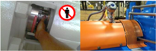
FIG. 2. Unguarded shaft area (left) vs. guarded (right).
Baseplate descriptions have been improved with revised wording and included conceptual images depicting the three basic designs:
- A flat deck plate with a sloped gutter drain that protrudes beyond the side rail flange and surrounds the entire baseplate.
- A sloped full deck plate, mounted between the side rails, which extends under the pump and drive train components.
- A sloped partial deck plate, mounted between the side rails, which extends only under the pump and coupling.
Options for other designs such as open top-plate, non-grouted and non-grouted with gimble mounts are addressed. The purchaser is to advise which design is required. Designation for Annex D, which provides pre-engineered baseplate sizes, has changed from being normative to informative based on the industry feedback that with today’s enhanced computerized layout of equipment by engineering, procurement and construction (EPC) companies and the quick turnaround by vendors to generate pump general arrangement drawings, this mandate for standardized baseplate sizes has diminished. The 12th Edition states baseplates may have Annex D dimensions if driver, pump size, auxiliaries and seal flush piping properly fit.
A new requirement for OH2 pumps addresses the location for placing auxiliaries in the front region (adjacent to pump suction nozzle area) of the baseplate. This is a major change that improves accessibility for maintenance of single-stage overhung pumps by preventing blocking of the area adjacent to the pump bearing housing, mechanical seal, and coupling and providing easy access to remove the coupling and back-pull-out assembly (including bearing housing and case cover with mechanical seal) for maintenance. This is particularly important for OH2 process pumps with seal reservoirs for Plan 52, 53 and control panels for non-contacting gas seals, along with seal flush plans with coolers such as Plan 23 (FIG. 3). For between bearing pumps, auxiliaries are preferred to be mounted on one side leaving the other side open for easy maintenance.
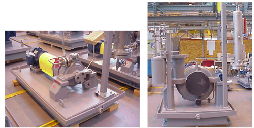
FIG. 3. Small and large OH2 pumps with auxiliaries mounted in front of the suction nozzle area.
The requirement for pipe gusseting the first connections off the casing has changed from being a bulleted paragraph in the 11th Edition to a requirement in the 12th Edition for all pumps with pipe sizes DN 25 (NPS 1) and smaller. This is a reliability issue to prevent small bore piping failures, especially pump drains which get stepped upon on occasion, though the requirement applies to all piping attached to the casing, such as vent piping.
Other key changes. The following are some of the many interesting additional changes made to the 12th Edition:
- Update: Materials
- Update: Vertical suspended pumps
- Update: Definitions, pump pressure ratings
- Update: Testing requirements
- Update: Improved wording, images and diagrams.
Materials of construction. There are several important changes made regarding materials, which are addressed in the two detailed Annexes (Annex G—Materials Class Section Guidance and Annex H—Material Specifications for Pump Parts). These changes include:
- Delete the material classes for cast iron material (classes I-1 and I-2), since API pump manufacturers no longer pour cast iron casings
- Re-defining boiling water and process water in terms of temperature limits, while replacing I-1 and I-2 with C-6 (12 chrome) materials
- For S-6 (carbon steel with 12 chrome trim) materials, use 12% chrome shafts (11th Edition allowed carbon steel up to 350°F)
- Delete material classes S-1 and S-3, as there are little usage steel pressure casings with cast iron and Ni-resist trim and internal parts.
- Remove the limiting pressure differential per linear measure for non-metallic wear parts
- Remove use of material designation CA15 for 12% chrome impellers in favor of CA6NM (as was already required for pump casings in 11th Edition) for improved castability, weldability and more resistance to cracking.
Under auxiliary connections, for C-6 materials, 316L piping and fittings may be used up to 260°C (500°F), with Inconel 625 material used for temperatures greater than 260°C (500°F) to eliminate sensitization of 316L at elevated temperatures and to prevent a decrease in corrosion resistance.
Vertically suspended pumps. Three areas regarding vertically suspended pumps have been expanded and modified. The first concerns changing the tolerance required for shaft to driver mating face perpendicularity and surface flatness from 25 µm (0.001 in) to 0.17 mm/m (0.002 in/ft) in the Drivers section of the 11th Edition. This change recognizes that the ability to hold the tolerance for shaft-to-driver mating face is dependent upon the diameter of the driver mounting flange.
Next, are the casing details relative to type VS6 pumps. An explanation is given to suction barrel or can construction details, which can have either a pipe with a butt welded “weld cap” design and radiography (RT) or a pipe with a fillet welded “flat plate” design inspected by either dye penetrant (PT), magnetic particle (MT) or ultrasonic (UT) non-destructive testing. The key with either design is for the suction barrel or can to meet the MAWP requirement. Suction barrels or cans may have either elliptical or flat bottom heads, again meeting the MAWP requirements, and use full-penetration welds. If elliptical bottom heads are specified, they will either be ellipsoidal or torispherical shapes. Longitudinal welds of seam-welded pipe for casing walls of pump heads and suctions barrels are to be 100% RT inspected.
The third area for improving vertical pump requirements is the dynamic section, which remains a bulleted paragraph (i.e., an optional requirement when specified by the purchaser). Clarification was added to describe that when a dynamic analysis is required by a customer, it means the complete pump, including the below ground components and the driver structure on either its foundation or support structure. Three new notes have been added to address the extent of detail required for the models, guidelines for vertical pump natural frequency analysis per the Hydraulic Institute and how to handle situations when separation margins are not achieved.
Definitions, pump pressure ratings. As part of the review process for producing the 12th Edition, Standard Paragraphs—which apply to all rotating equipment—were reviewed. They were compared to the 11th Edition to determine where possible changes in definitions would be required. The definitions needing attention were MAWP and maximum discharge pressure. In both cases, these pressures are now based on maximum specific gravity, and it is the responsibility of the customer to provide this information on the improved format of the API data sheets.
The 11th Edition (as well as all previous API 610 editions) required that OH, BB1 and BB2 pumps be rated for 41 bar (600 psi). The 11th Edition had a special note stating that by the time the 12th Edition is issued, OH, BB1 and BB2 pumps would be required to have a pressure rating equal to that of a PN 40. (300 lb) flange, which is 51 bar (740 psi) at 100°F (38°C). Further discussions revealed that most of these pump sizes generate heads that are relatively low. This translates to the current 41 bar (600 psi) pressure requirement to which most pump manufacturers comply. The final decision was made to revert to the 40 bar (600 psi) rating for these pump types. It should be noted that most manufacturers do have, as an option, higher pressure pump designs, especially for high suction pressure applications which require PN 100. (600 lb), PN 160. (900 lb) and even PN 250. (1500 lb) flanges and heavier wall thickness casing designs.
Testing requirements. Three additional performance testing points were added to help better verify pump performance in the region between rated flow and minimum continuous stable flow (MCSF).
Explanation has been added to address disassembly after performance testing of BB3 and BB5 pumps to ensure that all water is removed from internal passageways, as water cannot be removed simply by draining for these designs. However, for these multistage pumps, pump disassembly after tests may be invasive to the point of impacting mechanical integrity.
Clarifications have been added to the bearing housing resonance test regarding actions required if bearing housing resonance conditions cannot be detuned.
Improved wording and images, diagrams and normative references. One of the main objectives for the API 610 12th Edition task force was to improve wording throughout the document for clarity to assist international users. With this goal in mind, images and diagrams were added to show requirements more explicitly (e.g., baseplate designs), along with expanding the table of contents to include figures and tables, and adding a listing of acronyms and abbreviations
One area of confusion was the description of pump classifications and designations. Images for vertically suspended pump types VS6 and VS7 were improved to show both flat bottom and ellipsoidal can designs as acceptable. An image was added for “near centerline supported” BB1 pump (FIG. 4) to clearly differentiate from the foot-mounted single-stage axially split between bearings pump (FIG. 5).
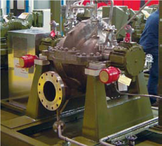
FIG. 4. Near-centerline-mounted BB1 pump.
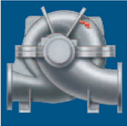
FIG. 5. Foot-mounted BB1 pump.
Similarly, a better description of single-stage axial split between bearings BB1 pump classification—foot- or near-centerline-mounted—was added to BB3 and BB4 pumps. “Centerline supported” was added to BB2 pumps. A further clarification was made so that the figures shown generically represent the various pump types and do not reflect actual construction details or certain pump features. This wording was added to help both contractors and end users apply variations of the images without concern. FIG. 6 depicts two additional nozzle orientations for BB1 pumps. FIG. 7 shows a typical top/top nozzle orientation for OH2 single-stage overhung process pumps. This combination was very common in the past, as it provided a cleaner field piping arrangement without typical end suction pump piping obstruction at the ground level, and for modular design systems where space is a premium. These orientations are still purchased today and are not considered as deviations or exceptions to API 610 12th Edition.
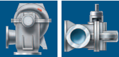
FIG. 6. Optional nozzle orientations for BB1 pumps.
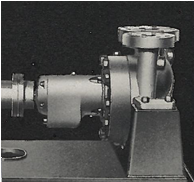
FIG. 7. Top/top nozzles OH2 pumps.
Regarding normative references, since the use of cast iron has been removed from the
12th Edition (as explained in the above paragraph on Materials), various ISO or ANSI/ASME standards for this material have also been removed. Certain ISO specifications addressing other materials have remained, since there are no ANSI, ASME or U.S. equivalent specifications.
Takeaway. This article has touched on the main and other changes from API 610 11th Edition to the 12th Edition. Most of them have impacted pump reliability and maintainability. Changes were made to reflect industry feedback and most end user specification requirements to elevate equipment to a level of minimizing the need of overlay specifications. However, as technology changes and more demanding services arise, the API 610 standard continues to evolve.
NOTE
This article includes updates to the published 2016 Texas A&M Turbomachinery & Pump Symposia paper on API 610 12th Edition.
Authors
Frank Korkowski (korkowskifrancis@gmail.com) is the Manager of Engineered Training at Applied K3nowedge Consulting. He is a consultant recently retired from Flowserve and previously was the Marketing Manager for the API 1 and 2 stage process pumps. He spent 45 yr in various pump roles with Ingersoll Rand, Ingersoll-Dresser Pumps and Flowserve. Mr. Korkowski earned a BS degree in industrial engineering from the New Jersey Institute of Technology, with post-graduate studies in engineering and business administration at Lafayette College and Fairleigh Dickinson University.
Tom Hess (thess@e2g.com) is the Principal Rotating Engineer for The Equity Engineering Group, Inc. Prior to joining Equity, Mr. Hess worked as a Rotating Reliability Engineer in an oil refinery. He has been fascinated with sealless pumps for nearly 30 yr. He earned his BSME from Villanova University, is a member of ASME and is a registered professional engineer in the Commonwealth of Pennsylvania. Mr. Hess is a member of the API 685, 610, 682 and 613 Task Forces.
Roger L. Jones (rogerjonessping@aol.com) is a Rotating Equipment Consultant and Task Force Chairman for API 610. Mr. Jones spent 32 yr in various positions at different Shell companies. In his career, he has held numerous technical and managerial positions in chemical plants and refineries, major capital projects and engineering consulting roles. He earned BS and MS degrees in mechanical engineering from Kansas State University and is a registered professional engineer in Texas. He is the previous chairman of the International Standards Coordinating Committee of the API and head of the U.S. delegation to the various ISO technical committees governing standards for refining and offshore equipment. He is a former member of the International Pump Users Symposium Advisory Committee.


Comments