Exclusive: MAA Refinery—Bunker fuel oil challenge Stable and compatible VLSFO production
Studies have been conducted on strategies for bunker fuel oil (BFO) production with reduced sulfur and catalytic fines concentration limits. However, these studies conclude that refiners must face challenges in terms of BFO stability and compatibility. In addition, heavy fuel oil (HFO) prices/demand will diminish, which force refineries to find alternate options for the disposal. Therefore, to find strategies for BFO production, KNPC’s Mina Al-Ahmadi (MAA) refinery had conducted feasibility and pilot studies. These pilot studies are small-scale, preliminary studies, which aim to investigate whether the blending ratio considered for the feasible components available in the MAA refinery to produce on-specification very low-sulfur fuel oil (VLSFO) BFO for longer periods. Subsequently, the results and analysis of the trial concluded that order of blending and stream qualities are the best ways for increasing the level of compatibility in BFO.
This article provides a comprehensive analysis of VLSFO quality constraints and the MAA refinery’s experience in VLSFO production.
Bunker fuel—An easy guide. Bunker fuel dates to steam-powered ships, which at the time were powered by coal and stored their ’fuel’ inside of ‘coal bunkers’ onboard. At present, in place of coalbunkers, ships have fuel tanks, but they are still often referred to as bunkers.
Maritime vessels use bunker fuel to power their motors. Some watercrafts use diesel (i.e. marine gasoil, which is considered a low-sulfur fuel oil) as their source of bunker fuel. However, for most commercial ocean-going vessels, they currently rely on HFO to generate power to propel their ships across the ocean. These are highly polluted, can cause respiratory diseases and are a component of acid rain that damages vegetation and wildlife.
Emission control area (ECA) limits were gradually reduced from its initial value of 1.5% sulfur to 1% in 2010 and then to 0.1% in 2015. The global sulfur limit in marine fuels was set to 3.5% in 2012. On January 1, 2020, the International Maritime Organization’s (IMO’s) new sulfur regulations banned ships from using fuels with a sulfur content above 0.5% (FIG. 1).
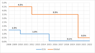
FIG. 1. The gradual reduction of BFO sulfur specifications.
Note: the utilization of approved alternative means of emissions reduction—which are at least as effective as using compliant fuels—is also permitted. An exhaust scrubber designed for reducing sulfur oxide (SOx) content to the level required is considered equivalent, and fuels with higher sulfur content may still be used on vessels equipped accordingly. However, usage of exhaust scrubbers is limited due to restrictions in disposing of washwater; however, most ports are not allowing vessels to discharge washwater near these facilities.
|
Sulfur content |
HFO (RM grades) |
MDO (DMB, DFB) |
MGO (DMA, DFA, DMZ, DFZ) |
|
Sulfur ≤ 0.1% |
ULSFO RM |
ULSFO DM VLSFO DM HSFO DM* |
|
|
0.1% < sulfur < 0.5% |
VLSFO RM |
||
|
0.5% < sulfur |
HSFO RM* |
||
TABLE 1. Fuel names after IMO sulfur regulation went into effect (January 2020)
*Fuels allowed only for ships with exhaust reduction technologies, yielding SOx reductions equivalent to using fuels with the respective sulfur limit
Refinery challenges for VLSFO bunker fuel production. Most fuels used in the market after the start of IMO’s sulfur regulation are VLSFO (A list of fuel names are listed in TABLE 1). The switch to VLSFO affected refinery production since it is unlikely that HFO products can simply be desulfurized to create compliant fuels. Instead, VLSFO will consist of blends of fuels produced from different refinery streams. These blends are expected to have higher fractions of paraffinic products, which will affect the properties of VLSFO. It is important to state that VLSFO must be compliant with ISO 8217:20171 and fit within the same residual marine (RM) grades as used prior to 2020. The following are some important parameters that have huge challenges while adhering to the ISO 8217:2017 specification of VLSFO.
Compatibility and/or stability: Depending on the origin and production process used, VLSFO blend streams can be aromatic or paraffinic in nature. This could lead to compatibility problems between different fuel streams.
Blending of aromatic streams with paraffinic streams result in sludge formation—after prolonged time in a tank, even if initially stable—due to a change in solubility properties of the subsequent blend.
Viscosity. The viscosity of fuel oils must be in accordance with ISO 8217:2017.1 VLSFO fuels are expected to have a broad range of viscosities, even within the same grade. Some types of VLSFO will have low viscosity levels, such as distillate marine (DM) fuel.
Cold flow properties. With VLSFO having high fractions of paraffinic components, exposure to prolonged cold conditions may lead to wax formation, which, in turn, could affect the cold flow properties of the fuel.
Calculated carbon aromaticity index (CCAI). The CCAI provides an indication of the ignition properties or ignition delay of fuels based on fuel viscosity and density. In view of the broad range of density and viscosity values of VLSFO, resulting CCAI values can also vary considerably.
Catalytic fines. The level of catalytic fines in VLSFO are unknown and might vary depending on the refinery streams from which the fuel was produced.
Blending of VLSFO. The major challenge refineries face is to keep the asphaltenes micelles in colloidal solutions of fuel oil. High aromaticity of fuel oil helps to achieve the same. In addition, if an aromatic cutter is poured into a paraffinic base, then the initial small volume of aromatics in a paraffinic medium will disturb the low aromaticity of the paraffinic base, thereby increasing the probability of asphaltene sludging (FIG. 2).
|
|
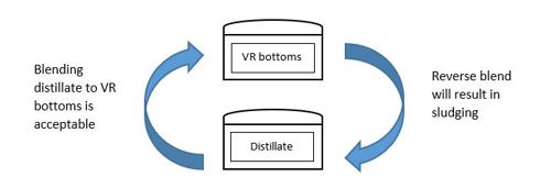
FIG. 2. Blending direction.
In the opposite situation, where paraffinic blend stock is poured into an aromatic medium, the aromaticity at the interface of the two liquids will be predominantly by the aromatics and will always keep asphaltenes in the solution.
Based on typical examinations of VLSFO blendstock properties, they can be classified as high aromaticity base (50%–60 %)—i.e., vacuum bottoms and visbreaker tar bottoms—and two types of cutter stocks (aromatics and paraffinic).
Aromatic cutters are typically from Fluid catalytic cracking units (FCCUs) and include light-cycle oil (LCO), heavy-cycle oil (HCO) and slurries or clarified oils (CLOs). These cutters are highly aromatic liquids (80% or higher). Paraffinic cutters are typically from atmospheric and vacuum distillation units (VDUs), such as atmospheric gasoil (AGO), light and heavy AGO and vacuum gasoil (VGO). These cutters have low aromaticity of around 30%–50%. Typical properties of blending components are detailed in TABLE 2.
|
Description |
ARD residual |
VR residual |
Gasoil |
Trim gasoil (TGO) |
|
Specific gravity |
0.9302 |
0.989 |
0.845 |
0.9068 |
|
Sulfur, wt% |
0.46 |
0.7 |
0.0005 |
0.16 |
|
Viscosity, centistokes (cSt) at 50°C |
175 |
5,000 |
4 |
96 |
|
Asphaltenes, wt% |
1.7 |
3.1 |
– |
– |
|
Vanadium, wt% |
7.5 |
36 |
– |
– |
TABLE 2. Typical properties of blending components
Considering asphaltene content and aromaticity, VLSFO fuel oil blends can be categorized as paraffinic blends, aromatic blends, and hybrid blends.
Paraffinic blends. These blends typically use vacuum tower bottoms and the cutter [e.g., light atmospheric gasoil (LAGO), heavy atmospheric gasoil (HAGO) or ultra-low-sulfur diesel (ULSD)].
Vacuum residue (VR) from the VDU can be blended with low-sulfur streams to produce the required product, keeping that resulting blend aromaticity above 40% by controlling the blend ratio and order of blending. TGO dropping in vacuum tower bottoms will help to achieve the required aromaticity. With VR blended with distillate, the final blending aromaticity could drop below 40% and can lead to sludging, depending on the blend ratio and the order of blending.
|
Blend component |
Aromaticity |
|
Vacuum tower bottoms |
Nearly 80% |
|
Gasoil |
30%–40% |
Aromatic blends. These blends typically use “cracked” blend components, such as visbreaker tar bottoms and highly-aromatic cutters (i.e., LCO and HCO). Any aromatic blend will have an excess of aromaticity (more than 50%) and be stable.
|
Blend component |
Aromaticity |
|
Visbreaker tar bottoms |
47%–56% |
|
LCO and HCO |
More than 80% |
Hybrid blends. These blends typically use paraffinic blend components such as atmospheric tower bottoms, vacuum tower bottoms and mixtures of both paraffinic cutters (e.g., AGO, LAGO and HAGO) and aromatic cutters (i.e., LCO and HCO). Depending on the blend recipe, a hybrid blend is not guaranteed to always have an excess of aromaticity (more than 50%) and be stable.
The changes in fuel production result in different nature and quality of fuels. New fuels (VLSFO) that are compliant with the 0.5% sulfur limit are likely to display a wide variability of physical and chemical properties, even between fuel batches of the same ISO specification.
|
Blend component |
Aromaticity |
|
Atmospheric tower bottoms and vacuum tower bottoms |
50%–60% |
|
Gasoil |
30%–40% |
|
Cycle oil |
More than 80% |
Potential of refineries to produce VLSFO. The considerable decrease of sulfur in fuel content had a substantial effect on bunker fuel production. In response to the regulation’s significant reduction in sulfur requirements, refineries must make capital investments and use innovative technologies/methods to reduce the amount of sulfur and particulates in fuel oil. Apart from this, HSFO production needs to be minimized in anticipation of a drop in value.
VLSFO must be compliant with ISO 8217:2017 to adhere to IMO requirements. The blending of available components in refineries plays a vital role in production. The major concern is the compatibility between different VLSFO blends. VLSFO blending is a challenge from fuel oil stability and compatibility points of view.
Kuwait National Petroleum Co.’s experience with VLSFO production
Kuwait National Petroleum Co. (KNPC) has two refineries—Mina Abdullah (MAB) and Mina Al-Ahmadi. Both refineries produce clean-burning fuels, conforming to Euro-5 standards. As per design, KNPC will produce a significant amount of LSFO, with a viscosity of 380 and 180 cSt. The components in the KNPC refinery to produce LSFO is atmospheric residue from the crude distillation units (CDUs), treated residue (ARDR) from the atmospheric residue desulfurization (ARD) units, VR from the VDUs, distillate, LCO and HCO from the FCCU.
The option of producing the desired VLSFO product from atmospheric residue is not possible due to high sulfur content (> 4 wt%). Diverse options tried by KNPC to produce VLSFO, along with associated limitations and subsequent product quality is presented in detail here.
The MAA refinery’s CFP ARD unit can produce residue with sulfur content significantly less than 0.5%, which is further processed in the vacuum unit to keep feed sulfur at a minimum. ARD distillate can be used as a cutter to blend with VR bottoms.
Option 1: Hydrotreated ARDR. KNPC’s new ARD unit’s (FIG. 3) product can be directly supplied as BFO without blending with another stream with sulfur less than 0.5 wt%. ARDR sulfur will depend on the level of desulfurization and will vary from start of run (SOR) to end of run (EOR).
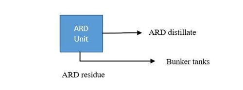
FIG. 3. ARD units.
|
Parameter |
Unit |
ARD |
|
Carbon residue, Conradson |
% mass |
3.98 |
|
Sulfur, total |
% mass |
0.4 |
|
Density at 15°C |
kg/l |
0.9259 |
|
Viscosity at 50°C |
cSt |
173 |
|
Sludge, hot filtration |
% mass |
0.036 |
|
Hydrogen sulfide (H2S), liquid phase |
ppm |
0.02 |
|
Vanadium |
mg/kg |
5.3 |
|
Ash |
% mass |
0.02 |
|
Sediment |
% mass |
0.04 |
|
Asphaltenes |
% mass |
1.72 |
|
CCAI |
calculated |
795 |
TABLE 3. typical properties of the ARD residue
To route ARDR to the appointed VLSFO tanks, a project modification is required with controls in the unit and offsite area. The required project modification is raised and expected to take a long time to completion:
- Impact: There will be a reduction in conversion unit feed rate—primarily hydrocrackers, FCCUs and coker units—since part of KNPC’s ARDR will not be processed in the vacuum re-run units, thus VGO/TGO/VR loss. Therefore, naphtha, ATK and diesel production will also be reduced.
Option 2: VR residue blending with diesel. VR from the VDUs can be blended with a low sulfur stream to produce the required product (FIG. 4). To reduce sulfur in VR bottoms, feed sulfur was kept exceptionally low. That has resulted in achieving sulfur in VR bottoms at 0.84%. Adding 10-ppm sulfur gasoil, the resulting sulfur was reduced to less than 0.5 wt% as per VLSFO requirements.
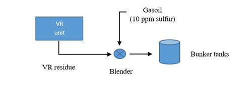
FIG. 4. VR / ARD units
|
Parameter |
Units |
Result |
|
Ash |
% mass |
0.02 |
|
Density at 15°C |
kg/l |
0.9047 |
|
Flash point, PMCC |
°C |
108 |
|
H2S |
mg/kg |
0.93 |
|
Pour point |
°C |
3 |
|
Relative density at 60°F |
– |
0.9052 |
|
Sulfur, total |
% mass |
0.48 |
|
Total sediment potential |
% mass |
0.04 |
|
Vanadium |
mg/kg |
7.2 |
|
Viscosity, kin. At 50°C |
cSt |
45 |
|
Aluminum and silicon |
mg/kg |
5.7 |
|
CCAI |
– |
793.1 |
TABLE 4. Results of the final blend
The BFO viscosity quality is extremely low at 45 cSt compared to a maximum of 380 cSt, and CCAI is close to max limit:
- Impact: It requires about 45% of 10 ppm gasoil as cutter stock. That may lead to the possibility of final blending aromaticity to drop below 40% and can lead to sludging. Therefore, this option has an inherent risk associated with that.
Option 3: Diesel as bunker fuel. Diesel can be supplied as bunker fuel at prevailing market prices. KNPC economics will not be affected if bunker price is the same as the export gasoil price. In this case, the bunker will be 10 ppm gasoil.
Option 4: Using low-sulfur ARDR, ULSD and UCO. MAB had successfully completed the trial run for the lab blend with ARD residue and mix of TGO and UCO to produce low-sulfur fuel oil. However, the blend viscosity was around 20 cSt–40 cSt. The initial blended batch was stable and the desired results were achieved. However, compatibility issues were observed in the subsequent batches. Executing the modifications shown in FIG. 5, MAB successfully prepared the first batch of VLSFO.
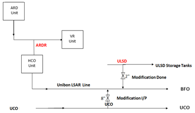
FIG. 5. MAB units blend.
|
Parameters |
MAB VLSFO |
MAB VLSFO |
VLSFO import: First cargo |
|
Sulfur, % mass |
0.39 |
0.5 |
0.46 |
|
Density at 15°C, kg/l |
0.894 |
0.896 |
0.937 |
|
Flash point, °C |
110 |
> 110 |
104 |
|
Kin. Viscosity at 50°C, cSt |
37.2 |
40 |
345 |
|
Total sediment potential, % mass |
0.1 |
0.06 |
NA |
|
H2S (liquid phase), ppm |
0.2 |
0.2 |
0.5 |
|
Ash, % mass |
0.06 |
0.02 |
0.03 |
|
Aluminum and silicon, mg/kg |
4 |
4.6 |
NA |
|
Vanadium |
5.7 |
6.7 |
NA |
|
CCAI |
785 |
785 |
800 |
TABLE 5. BFO results
Option 5: VR and TGO. The MAA refinery finally achieved the most economic and feasible way of producing VSLFO using ARD distillate, VR vacuum residue and TGO streams (FIG. 6). To achieve the above, the ARD unit was run with ARD residue product with sulfur of 0.35 wt% maximum. The VR unit must process low-sulfur ARD residue from the ARD unit without mixing with high-sulfur ARD residue from other MAA ARD units.
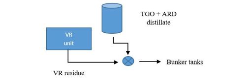
FIG. 6. VR residue with TGO blend.
|
Parameter |
Result |
|
Aluminum and silicon, mg/kg |
0.1 |
|
Ash, % mass |
0.02 |
|
CCAI |
800.1 |
|
Density at 15°C, kg/L |
0.9353 |
|
Flash point (PMCC), °C |
114 |
|
H2S, mg/kg |
0.3 |
|
Phosphorus, mg/kg |
0 |
|
Pour point, °C |
-3 |
|
Relative density at 60°F |
0.9358 |
|
Sulfur (total), % mass |
0.45 |
|
Total sediment potential, % mass |
0.1 |
|
Vanadium, mg/kg |
10 |
|
Viscosity, kinematic at 50°C, cSt |
276 |
TABLE 6. BFO results
By the above operating condition, the VR will have sulfur at 0.7 wt% maximum and the viscosity will be around 4000 cSt–5,000 cSt at 50°C. Blending low-sulfur ARD distillate and TGO from the VR unit (sulfur limit of 0.15 wt%), the required VLSFO production was achieved.
MAA refinery issues while handling imported materials. To adhere to VLSFO bunker fuel requirements, a cargo was imported with 0.46 wt% sulfur in December 2019 into the MAA refinery’s bunker tanks. Prior to import, both tanks were cleaned and the associated system was flushed thoroughly using 500-ppm gasoil. Upon completion of import, both the tanks were certified as per IMO specifications.
During this period, the MAB refinery produced a batch of VLSFO as per Option 4. KNPC arranged the vessel and upon loading, the ship’s composite sample at the MAB refinery port met all specifications (sulfur at 0.495 wt%); however, a prior discharge at the MAA refinery contained sulfur exceeding the limits (0.508 wt%). After quality control, clearance was received into bunker tanks. Upon receipt, the fuel was 0.5 wt%. A vessel was loaded at the end of January 2020 and the composite sulfur sample was 0.51 wt%. Several samples at various locations were collected and the sulfur results marginally exceeded limits. With the sulfur content exceeding limits and with no facility for correcting the product, the MAA refinery requested to dispose the product. Upon arranging a vessel to load the product, the tank samples showed sulfur content was 0.44 wt% and 0.51 wt%, respectively. However, during samples taken over the next several weeks showed inconsistencies in mixtures.
|
Parameter |
VLSFO 1 |
VLSFO 2 |
|
Aluminum and silicon, mg/kg |
24.88 |
43.8 |
|
Ash, % mass |
0.03 |
0.03 |
|
Density at 15°C, kg/L |
0.937 |
0.9354 |
|
Flash point (PMCC), °C |
104 |
100 |
|
H2S, mg/kg |
0.5 |
0.5 |
|
Relative density at 60°F |
0.9376 |
0.936 |
|
Total sulfur, % mass |
0.46 |
0.46 |
|
Total sediment potential, % mass |
0.04 |
0.04 |
|
Vanadium, mg/kg |
3.8 |
3.7 |
|
Kin. viscosity at 50°C, cSt |
345 |
348 |
|
CCAI |
800 |
798 |
TABLE 7. MAA refinery bunker tank results
From these results, it can be inferred that it is imperative that all receipts of this grade fuel oil should have a maximum of 0.47 wt% (95% confidence level). This clarifies the challenges met and efforts exerted by all concerned at the MAA and MAB refineries to meet IMO requirements.
Takeaway. With the new IMO 2020 low-sulfur regulation, bunker production must use low-sulfur blend components to be compliant. Sludge issues can be avoided by calculating the fuel’s compatibility and stability. The asphaltene content and aromaticity of fuel oil is critical to its fitness for use.
KNPC achieved the most economically feasible way of producing VLSFO by using distillate, VR and TGO streams originating from latest clean fuels project units. This VLSFO met the IMO 0.5 BFO specifications with a minimum viscosity of 250 cSt and was a stable product due to low asphaltene content of the VR.
With these accomplishments, KNPC is in the position to adhere to the IMO mandatory requirements of VLSFO IMO BFO, with a financial benefit. In addition, it will help the MAA refinery to modify the production slots based on the economics and market demands.
BIOS
Mohammad B. Matar is a chemical engineer. He is the Team Leader Operational Planning at KNPC, with experience in refinery operations, planning and process engineering.
Ali Al Mane is a chemical engineer with more than 15 yrs. of experience. Ali is in operational planning and played a significant part in the MAA Clean Fuel Project commissioning.
Muthusamy Rajendran is a chemical engineer with 30 yrs. of experience in planning at KNPC and has worked in various fields of planning/operations and commissioning.
ACKNOWLEGEMENTS
The authors would also like to thank the following people:
Kanagasabai Rathina Sabapathi is the Technical Process Specialist at KNPC, with experience in process engineering, operations, and design.
Kishor Datta Purkayastha is a Process Engineer at KNPC, with focus on process engineering in hydroprocessing and hydrocracking units.
Mayank Garg is a chemical engineer with more than 12 yr of experience in various roles of simulation/planning and process design related to the oil and gas industry.


Comments