
January 2026
Carbon Capture/CO2 Mitigation
Process implications with oxy-combustion in an FCC regenerator
The fluid catalytic cracking unit (FCCU) is the significant contributor of carbon dioxide (CO2) emissions in refineries resulting from coke combustion in the regenerator. The FCCU is accountable for 25%–35% of refinery CO2 emissions. The capture of CO2 from flue gas is not economically viable due to its low CO2 concentration, its substantial volume and contaminant content, operating expenses (OPEX) and significant investment.
Necessary changes in FCC operation are essential to reduce CO2 emissions in a net-zero scenario. One such possible operational change involves CO2 enrichment in FCC flue gas by enabling coke combustion with oxygen (O2)-enriched air. In this process, a part of the CO2-enriched flue gas is mixed with O2-enriched air before being fed to the regenerator to avoid excessive regenerator temperature. The mixture of O2, CO2 and nitrogen (N2) is called synthesized air (SA), and this regeneration process called oxy-combustion results in regenerator flue gas containing higher CO2 concentration, thus making recovery easier easier and economical. CO2-enriched flue gas (CO2eFG) can be utilized for sequestration, conversion to chemicals or eFuels. Moreover, the use of oxy-combustion results in an incremental throughput benefit. This article describes the process implications of oxy-combustion, such as change in composition, molecular weight, specific heat and enthalpy change of SA and CO2eFG, regenerator temperature and catalyst-to-oil ratio.
The FCCU remains a pivotal process in refineries, effectively converting the bottom of the barrel into valuable products [mainly liquefied petroleum gas (LPG) and gasoline.1 In the last decade, the severity of FCC operations with respect to reaction temperature and catalyst-to-oil ratio have increased significantly to maximize light olefins for petrochemicals production.2 The typical feedstock for this process is vacuum gasoil (VGO), reduced crude oil and its mixture.
The FCCU consists of a riser reactor and regenerator section where cracking takes place in the riser reactor, and catalyst activation occurs in the regenerator at elevated temperature. The powdered hot catalyst is mixed with the feed at the bottom of the riser reactor, producing a vapor stream consisting of lower boiling hydrocarbons. During the cracking reactions, carbonaceous residue (called coke) deposits on the catalyst’s surface, leading to catalyst deactivation. Since the process is cyclic, the coked catalyst is transferred to the regenerator wherein coke is combusted at higher temperatures > 625°C (1,157ׄׄ°F) using air, thereby generating flue gas consisting of CO2, carbon monoxide (CO), water (H2O), sulfur oxides (SOx) and nitrogen oxide (NOx).
The hot and reactivated catalyst is sent back to the riser reactor for cracking. CO2 and other combustion products are emitted to the atmosphere as flue gas. As stated above, FCC accounts for 25%–35% of the overall refinery CO2 emissions.3,4 In the present scenario, although carbon content over the reactivated catalyst has reduced to < 0.1 wt%, the FCCU still presents complexities in terms of operation.5 During the regeneration of coked catalyst, CO2 is emitted into the atmosphere, resulting in environmental challenges.
Increasing CO2 concentration in the atmosphere is becoming a major concern for global environmental sustainability. If no suitable action is taken for CO2 capture and utilization, its concentration in the atmosphere is expected to increase to 550 mg/liter by 2050.6 Throughout 2020–2030, refineries globally will emit 16.5 gigatons of CO2 cumulatively.7 Since the 1970s, carbon capture and storage (CCS) technology has been adopted by the oil and gas sector for enhanced oil recovery (EOR), which drives to utilize this technology in various CO2 mitigation applications.8
While analyzing different CO2 mitigation strategies by refineries to achieve net-zero emissions, the co-processing of bio-generic feedstocks accounts for ~60% of the mitigation alternatives, followed by CCS (23%), and through green electricity and green hydrogen (H2).9 For refiners, another alternative to improve CO2 capture is through the use of advanced solvents in a carbon capture system. The economics of CCS mainly depend on government policies and carbon credits.10
In FCC, pre-combustion carbon capture is not an option because catalyst regeneration is an unavoidable carbon source. However, CO2 capture routes like post-combustion carbon capture and oxy combustion can be implemented in FCC operations. Post-combustion capture, however, is not economically viable due to low CO2 concentration, its substantial volume and contaminant content, significant investment and OPEX.11 One of the studies in literature shows that the CO2 capture cost for oxy-combustion is ~45% lower compared to a post-combustion amine absorption alternative.12,13
Chemical looping combustion is also a novel approach for CO2 capture in FCC, where catalyst is mixed with oxygen carriers like Cu2O, CoO and Mn3O4.14 Implementation of such CO2 capture processes in FCC requires in-depth understanding of the implications on operational variables. The current study specifically focuses on oxy-combustion implementation in an FCCU regenerator and maximizing the CO2 concentration in flue gas for carbon capture and utilization. This article details the oxy-combustion implications over multiple FCC parameters, such as dense bed temperature, flue gas composition, feed throughput and catalyst-to-oil ratio. The quantitative impact analysis over these operating variables will provide refiners an idea about oxy-combustion feasibility in FCCUs. The results will aid in further evaluation of techno-economic feasibility of oxy-combustion integration with FCC and its overall impact on refinery CO2 emissions.
Oxy-combustion. Oxy-combustion is a promising process that can be integrated into an FCCU for CO2 capture. Oxy-combustion requires an air separation unit (ASU), oxygen injector and flue gas recycling system. Despite the relatively high capital (CAPEX) and OPEX of an ASU, it is an attractive proposition to capture CO2 due to feed throughput enhancement. A kinetic model study derived from literature, based on pilot scale oxy-combustion implementation in FCC, shows an incremental conversion rate compared to conventional FCCU operation.15,16
In a conventional FCCU regenerator, air used for coke combustion typically contains about 21 mol% O2, and 79% mol% N2 and argon on a dry basis. During combustion, only O2 gets consumed, whereas N2 acts as an inert and heat sink. Air used for coke combustion can also be enriched with O2 to impove the regenerator capacity by up to 35%.17 However, this will not help in the CO2 enrichment in flue gas. In the proposed oxy-combustion process, air will be replaced with SA. In oxy-combustion, the flue gas ex-regenerator contains higher levels of CO2 depending on the O2 and CO2 concentration in the SA.
It also contains 2%–5% moisture and goes up to 5%–10% after wet gas scrubbing to reduce the pollutants, SOx and Nox. Wet flue gas with traces of acidic components like SOx and NOx can form acids when combined with moisture. These acids can corrode the compressor and associated piping. Therefore, moisture must be separated from flue gas before recycling to make SA. The process scheme for oxy-combustion is given in FIG. 1.

FIG. 1. Process scheme for oxy-combustion.
The composition of SA and CO2eFG depends on the purity of the O2 stream from the ASU and the flue gas recycle ratio. A few possible SA compositions and the corresponding CO2eFG composition are given in FIGS. 2 and 3, respectively. Air with 4 vol% moisture and 5.9 wt% coke yield with 6 wt% H2 content in coke are considered for these calculations.

FIG. 2. SA composition (dry basis).

FIG. 3. CO2eFG composition (wet basis).
The O2 concentration in SA varies from 25 vol%–28.5 vol% as compared to 21 vol% in Base Case operation. The CO2 concentration in SA works out to be in the range of 42.5 vol%–70.5 vol% as compared to 0 vol% in Base Case operation, and CO2eFG works out to be in the range of 60 vol%–90 vol% as compared to 15 vol% in Base Case operation, depending on the flue gas recycle ratio.
FCC regenerator coke combustion capacity is typically limited by the air rate and gas superficial velocity in critical components such as air distributors and cyclones. N2 replacement with CO2 leads to an increase in flue gas molecular weight (MW), the specific heat capacity (Cp) of SA and CO2EFG and, therefore, affects the heat balance of the unit. FIGS. 4 and 5 show how average MW and Cp of SA and CO2eFG change with CO2 concentration on a wet basis.

FIG. 4. Molecular weight, MW.

FIG. 5. Specific heat, Cp.
As seen in FIG. 4, the average MW of SA increases from 35.8 g mol-1 to 40.4 g mol-1 when CO2 changes from 42.5 vol% to 70.5 vol% compared to 28.4 g mol-1 in Base Case operation containing 0 vol% CO2. Similarly, the average MW of CO2eFG increases from 39.6 g mol-1 to 45 g mol-1 when CO2 changes from 60 vol% to 90 vol% compared to 32 g mol-1 in Base Case operation containing 15 vol% CO2. The corresponding Cp of SA increases from 8.5 cal mol-1K-1 to 9.5 cal mol-1K-1 as compared to 7 cal mol-1K-1 in Base Case operation. For CO2eFG, it increases from 10.9 cal mol-1K-1 to 12.5 cal mol-1K-1 as compared to 8.7 cal mol-1K-1 in Base Case operation. This, in turn, increases the enthalpy of outgoing flue gas. Therefore, while implementing oxy-combustion in FCCUs, the implication of increased flue gas enthalpy must be understood and necessary changes in the plant operation should be incorporated to maintain the desired regenerator temperature.
The applicability of oxy-combustion in FCC/Resid FCC (RFCC) units. The FCCU can be designed for lighter feedstock as well as heavier or residue feedstock. Lighter feedstocks such as VGO have lower coke making tendency compared to heavier or residue feedstocks. Maintaining the desired regenerator temperature [650°C–700°C (1,202°F–1,292°F)] for the full combustion of coke is crucial while processing lighter feedstocks. Sometimes, the regenrator might not reach the desired temperature, leading to incomplete combustion of coke on the catalyst. The recycling of clarified oil (CLO) becomes necessary to maintain the regenerator temperatures. In view of this, a reduction in regenerator temperature in the FCCU is an infeasible solution.
To understand the implication of oxy-combustion on the overall heat balance of an FCCU, multiple cases at different O2 levels in SA have been worked out. The critical process parameters of the FCCU processing VGO and residue feeds are given in TABLE 1. The heat of combustion, enthalpy of flue gas and air, and the reactor heat demand of the unit corresponding to Base Case operation without oxy-combustion are given in TABLE 2.


As seen in FIGS. 4 and 5, the MW and Cp of SA and CO2eFG increases by as much as 35%–40% in oxy-combustion. The enthalpy of CO2eFG also increases in the same proportion. The SA requirement also reduces significantly due to higher O2 levels.
There can be multiple possible scenarios in which oxy-combustion can be implemented without deteriorating the FCCU and RFCCU performance. The details are discussed below.
Scenario 1: Constant regenerator temperature at the same feed throughput. As discussed above, the enthalpy of CO2eFG increases due to higher Cp of CO2, which in turn affects the FCC heat balance. While maintaining the same constant regenerator temperature as that of Base Case operation, heat balance calculations were carried out for VGO feed and resid feed. To maintain the same regenerator temperature, the enthalpy of CO2eFG is to be kept constant irrespective of CO2 levels and ASU O2 stream purity. This is achieved by adjusting the flue gas recycle ratio. The ratio of SA to Base Case air and CO2eFG to Base Case FG, along with flue gas recycle ratio as a function of ASU O2 stream purity, are shown in FIG. 6.

FIG. 6. Ratio of SA and CO2eFG.
It is seen that in oxy-combustion, SA and CO2eFG flow decreases by 20%–30% when the ASU O2 stream purity is increased to 99%. Catalyst entrainment and its loss in the regenerator are expected to come down due to decreased flue gas rate or decreased superficial velocities.
Scenario 2: Constant flue gas rate at higher feed throughput. As seen in Scenario 1, while implementing oxy-combustion at a constant flue enthalpy or constant regenerator temperature, SA and flue gas decreases, leading to reduced superficial velocity in the regenerator. This provides an opportunity to operate the unit with higher feed throughput. Accordingly, feed throughput can be maximized to the extent that the flue gas molar mass rate is the same as that of Base Case operation and, therefore, superficial velocity in the regenerator is not increased beyond Base Case operation. The incremental heat produced from additional coke is balanced between riser reactor heat demand and the enthalpy of flue gas. This matching can be done by altering the flue gas recycle ratio. The change in feed throughput, the corresponding FG enthalpy and FG recycle ratio as a function of ASU O2 stream purity are shown in FIG. 7.
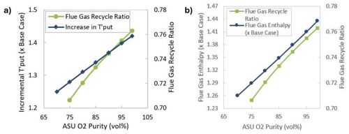
FIG. 7. The effect of oxy-combustion at constant flue gas rate scenario in an FCCU: (a) feed throughput increment, and (b) flue gas enthalpy increment.
It is seen that the feed rate can be increased up to 40% with 99% ASU O2 stream purity while maintaining flue gas molar flowrate as that of Base Case operation. The FG enthalpy also increases in the same proportion. Catalyst entrainment and its loss in the regenerator is expected to increase due to higher flue gas density.
Scenario 3: Constant flue gas rate at same feed throughput. In RFCCUs, the regenerator temperature is generally > 700°C (> 1,292°F) due to higher Conradson carbon and metals. Higher regenerator temperatures above > 700°C (> 1,292°F) lead to excessive catalyst deactivation and a lower catalyst-to-oil ratio and, therefore, lower conversion. Unlike FCCUs processing lighter feeds, a reduction in regenerator temperature in an RFCCU due to oxy-combustion is not an issue—rather, it is beneficial to reduce catalyst deactivation and improve conversion.
In this scenario at the same feed throughput, the molar flue gas rate is maximized to the level of Base Case operation by altering the flue recycle ratio. This in turn increases the flue gas enthalpy and reduces the regenerator temperature. The lower regenerator temperature reduces catalyst deactivation and increases the catalyst-to-oil ratio, leading to higher conversion.
In this case, the flue gas enthalpy increases up to 1.4 times as that of the Base Case indicated in FIG. 8, and the regenerator temperature is reduced by up to 30°C depending on the ASU O2 concentration, as indicated in FIG. 9. To maintain the riser reactor temperature, the catalyst-to-oil ratio increases from 10 to 12 weight per weight. The above observations are applicable for both FCCUs and RFCCUs.

FIG. 8. Change in regenerator temp and catalyst-to-oil ratio.

FIG. 9. Flue gas enthalpy at constant flue gas rate scenario in an RFCCU.
Scenario 4: Constant flue gas rate with heavier feed. Alternatively, heavier feeds can also be processed. A change in coke yield and flue gas recycle ratio as a function of ASU O2 stream purity is given in FIG. 10. It can be seen from this figure FIG. 10. It can be seen that coke yield can be increased by up to 0.7 wt%, amounting to incremental feed CCR by approximately 1 wt% at the same feed rate while maintaining the same regenerator temperature as that of Base Case operation.

FIG. 10. Incremental coke yield at same feed throughput.
In this case, the flue gas recycle ratio is lower than that of Scenario 3 but higher than that of Scenarios 1 and 2, as indicated in FIG. 11. The above observations are applicable for both FCCUs and RFCCUs.

FIG. 11. Flue gas recycle ratios in different scenarios.
Takeaways. The FCCU contributes 25%–35% of refinery CO2 emissions. By adopting oxy-combustion in an FCC regenerator, the CO2 concentration can be increased from 15 vol% to 90 vol% in flue gas. Flue gas molecular weight and specific heat increases from 32 g mol-1 to 45 g mol-1 and 8.7 cal mol-1K-1 to 12.5 cal mol-1K-1 due to higher CO2 concentration. Because of the higher CO2 concentration, the flue gas enthalpy increases up to 1.4 times of the Base Case flue gas enthalpy depending on the flue gas composition and the regenerator temperature. For a given feed throughput, the overall flue gas molar flowrate can be reduced up to 30%, leading to reduced gas superficial velocity in the regenerator.
This will reduce the load of the regenerator’s air distributor, cyclones, flue gas slide valve, orifice chamber, etc. It creates an opportunity to raise the feed throughput by 40% or increase the feed heaviness without changing the regenerator vessel. In residue feeds, the drop in regenerator temperature can be utilized for circulating more catalyst and, thereby, achieving higher conversion. In FCCUs that process VGO feed, oxy-combustion can be implemented in two different ways: maintaining the same regenerator temperature with a 30% lower flue gas rate on a molar basis and 40% higher throughput. In an RFCCU that processes resid feed, oxy-combustion can be implemented in two different scenarios: either to lower regenerator temperature and increase the catalyst-to-oil ratio or through processing heavier feedstock.
ACKNOWLEDGEMENT
The authors acknowledge the IOCL R&D Centre for providing state-of-the-art facilities and granting permission to publish this article.
LITERATURE CITED
1 Fals, J., M. L. OspinaCastro, A. RamosHernández, L. PachecoLondoño and S. Bocanegra, “Deactivation and regeneration dynamics in hierarchical zeolites: coke characterization and impact on catalytic cracking of vacuum gas oil,” Heliyon, Vol. 10, No. 18, September 2024.
2 Soni, D., P. J. Angevine, R. Rao, G. Saidulu, D. Bhattacharya and V. Krishnan, “Maximise olefins through catalytic cracking Indmax FCC process,” Digital Refining, April 2008, online: http://www.digitalrefining.com/article/1000205/
3 Güleç, F, W. Meredith and C. E. Snape, “Progress in CO₂ capture technologies for fluid catalytic cracking units—A review,” Frontiers in Energy, April 2020, online: https://www.frontiersin.org/journals/energy-research/articles/10.3389/fenrg.2020.00062/full
4 Güleç, F, W. Meredith and C. E. Snape, “CO₂ capture from fluid catalytic crackers via chemical looping combustion: regeneration of coked catalysts with oxygen carriers,” Journal of the Energy Institute, Vol. 107, April 2023, online: https://www.sciencedirect.com/science/article/pii/S1743967123000168
5 Oloruntoba, A., Y. Zhang and C. S. Hsu, “Stateoftheart review of fluid catalytic cracking (FCC) catalyst regeneration intensification technologies,” Energies, Vol. 15, No. 6, March 2022, online: https://www.mdpi.com/1996-1073/15/6/2061
6 Talei, S., D. Fozer, P. S. Varbanov, A. Szanyi and P. Mizsey, “Oxyfuel combustion makes carbon capture more efficient,” ACS Omega, Vol. 9, Iss. 3, January 2024, online: https://pubs.acs.org/doi/10.1021/acsomega.3c05034
7 Lei, T., et al., “Adaptive CO₂ emissions mitigation strategies of global oil refineries in all age groups,” One Earth, Vol. 4, Iss. 8, pp. 1114–1126, August 2021, online: https://www.sciencedirect.com/science/article/pii/S2590332221004103
8 Sunny, N., A. Bernardi, D. Danaci, M. Bui, A. GonzalezGaray and B. Chachuat, “A pathway towards netzero emissions in oil refineries,” Frontiers in Chemical Engineering, Vol. 4, February 2022, online: https://www.frontiersin.org/journals/chemical-engineering/articles/10.3389/fceng.2022.804163/full
9 Yáñez, É., H. Meerman, A. Ramírez, É. Castillo and A. Faaij, “Fully integrated CO₂ mitigation strategy for an existing refinery: A case study in Colombia,” Applied Energy, Vol. 313, May 2022, online: https://www.sciencedirect.com/science/article/abs/pii/S0306261922002215
10 Couch, K., “Refinery of the future: bankable, flexible, and sustainable,” PTQ, 2Q 2023.
11 Güleç, F., J. A. Okolie and A. Erdogan, “Technoeconomic feasibility of fluid catalytic cracking unitintegrated chemical looping combustion—A novel approach for CO₂ capture,” Energy, Vol. 284, December 2023, online: https://www.sciencedirect.com/science/article/pii/S0360544223020571
12 de Mello, L. F., et al., “A technical and economical evaluation of CO₂ capture from FCC units,” Energy Procedia, Vol. 1, Iss. 1, pp. 117–124, February 2009, online: https://www.sciencedirect.com/science/article/pii/S1876610209000198
13 Ferguson, S. and M. Stockle, “Carbon capture options for refiners,” Digital Refining, March 2012, online: http://www.digitalrefining.com/article/1000271/
14 Güleç, F., W. Meredith, C-G Sun and C. E. Snape, “A novel approach to CO₂ capture in fluid catalytic cracking—Chemical looping combustion,” Fuel, Vol. 244, pp. 140–150, May 2019, online: https://www.sciencedirect.com/science/article/abs/pii/S0016236119301693
15 Fu, C. and R. Anantharaman, “Modelling of oxycombustion fluid catalytic cracking units,” Computer Aided Chemical Engineering, Vol. 40, pp. 331–336, 2017, online: https://www.sciencedirect.com/science/chapter/bookseries/abs/pii/B978044463965350057X
16 de Mello, L. F., R. Gobbo, G. T. Moure and I. Miracca, “Oxycombustion technology development for fluid catalytic crackers—Large pilotscale demonstration,” Energy Procedia, Vol. 48, pp. 7815–7824, 2013, online: https://www.sciencedirect.com/science/article/pii/S1876610213008059
17 Linde, “Refinery Enrichment Technology: Enriching your refinery process,” online: https://www.lindeus.com/industries/refining/refinery-applications/fcc-oxygen-enrichment/
The Authors

Saidulu Gadari is the General Manager in Indian Oil Corp. Ltd.’s Research and Development Centre. His area of work includes the concept-to-commercialization of high-severity FCC process technology and its optimization and troubleshooting. Before joining Indian Oil, he worked in the Department of Atomic Energy as production engineer. He holds an MS degree in chemical engineering from the IIT, Madras. He is a fellow of the Indian Institute of Chemical Engineers.

Jayesh Yelmewar works as an Assistant Manager, Research in Indian Oil Corp. Ltd.’s Research and Development Centre. His area of work includes operation of micro reactor and pilot plants, process optimization and troubleshooting of FCCUs. Prior to joining IOCL, he worked as Manufacturing Execution System Developer at Cognizant Technology Solutions Corp. He holds dual degrees (BTech and MTech) in chemical engineering from IIT Bombay. He is a member of the Indian Society of Analytical Scientists.

Sarvesh Kumar is working as Chief General Manager in Indian Oil Corp. Ltd.’s Research and Development Centre. His area of work includes the concept to commercialization of various technologies in the refining segment and has received various awards for commercialization of technologies. He holds an MTech degree in chemical engineering from the IIT, Kanpur. He is a member of the Indian Institute of Chemical Engineers.

S Mukthiyar works as Senior Research Manager in Indian Oil Corp. Ltd.’s Research and Development Centre. His area of work includes process development, design of pilot plants, and the optimization and troubleshooting of FCCUs. Prior to joining IOCL, he worked as an environmental engineer for a leather tanning industry. He holds an MTech degree in chemical engineering from IIT Kharagpur.

T H V D Prasad works as a Chief Research Manager in Indian Oil Corp. Ltd.’s Research and Development Centre. His area of work includes process optimization, troubleshooting, re-vamp, development and commercialization in the FCC process and thermal cracking process. He holds an MTech degree in chemical engineering from the Indian Institute of Technology, Madras.


Comments