March 2026
Process Optimization
A flexible crude-to-chemicals and fuels technology
The co-authors’ company’s proprietary catalytic crude-to-chemicals (CTC) technologya is emerging as an innovative solution for directly converting crude oil into valuable chemicals. This advanced fluidized catalytic cracking (FCC) platform enables the efficient conversion of crude oil into high yields of olefins and aromatics (> 70 wt%), while maintaining the flexibility to produce fuels for changing market needs. This article highlights the collaborative approach taken by the authors’ companies in advancing this technology toward commercial deployment.
A fast-tracked development plan was established to develop a technology to convert crude oil into chemicals and address future limitations in traditional petrochemicals supply. Collaborations among industry leaders in refining and petrochemicals technology were key to this accelerated development. Additional efforts included mitigating risks via pilot plant trials, cold flow (CF) model validation and the use of advanced computational fluid dynamics (CFD) in modeling and equipment design.
The catalytic CTC technologya converter process fractionates crude oil into two main fractions (light and heavy) and processes them in a downflow fluidized bed. A key step was the design and integration of an industrial plant utilizing the co-authors’ company’s high-severity FCC unit (FCCU)b, which enabled optimization of commercial-scale processes and accurate yield projections. Testing in a circulating pilot unit and a large-scale CF model, both built and operated in China, confirmed optimal operating conditions for each fraction and validated hydrodynamic parameters for equipment design.
Through this integrated, de-risked approach—and close collaboration with partners—the CTC technologya has achieved commercial readiness. The result is a robust pathway to convert crude oil directly into chemicals, enabled by advanced engineering, simulation and the practical application of the commercial high-severity FCC designb with support from the co-authors’ companies.
Background. Traditionally, distillates obtained from petroleum refining and natural gas fractionation are separated and used as feedstocks for petrochemical production. The most common of these are ethane (from natural gas) and naphtha (from crude oil).
Other significant feedstocks include liquefied petroleum gas (LPG), gasoil and hydrowax (hydrocracker residue). These materials are typically converted into chemicals through steam cracking, also known as steam pyrolysis. The primary product of steam cracking is ethylene, while the use of LPG and heavier fractions also yields propylene, butadiene and butenes—collectively referred to as light olefins. Cracking heavier feeds also produces pyrolysis gasoline, which serves as an important source of aromatics, such as benzene, toluene and xylenes.
The choice of feedstock in a given region depends mainly on availability and local pricing. Ethane is often favored for ethylene production due to its lower energy cost compared to naphtha, simplified processing and higher yields. However, ethane yields only ethylene, with no additional petrochemical products. As a result, many regions must crack naphtha or import intermediates and end-products from areas with supply. This is why, despite its cost advantage, naphtha remains the dominant feedstock for producing both olefins and aromatics, accounting for roughly 75% of global usage.
Reducing reliance on conventional refining—particularly eliminating the need for distillation units that process crude oil into petrochemical feedstocks—would cut both capital and operating costs (CAPEX/OPEX), as well as greenhouse gas (GHG) emissions. To achieve this, the authors’ company has launched its catalytic CTC programa, aimed at developing economically viable methods to directly convert crude oil into basic petrochemicals without the costly, energy-intensive refining steps. A key benefit of this approach is providing an alternative feedstock source by utilizing existing crude oil reserves to expand the chemicals business. One such innovation is the catalytic CTC technologya, which builds on the proven high-severity FCC platformb and begins by flashing crude oil into light and heavy fractions before further processing.
Method. An accelerated development roadmap was established for the CTC technologya to align with the global strategic shift toward converting more crude oil into chemicals and to mitigate anticipated shortages in conventional petrochemical feedstocks. This roadmap integrates a carefully designed blend of experimental research, advanced simulation methods, utilization of the commercial CTC technologya design and operations, and close collaboration with leading industry partners like the co-authors’ companies.
Results. The CTC technologya is a fluidized-bed catalytic cracking process that utilizes at least two downflow reactors (DFRs) sharing a common regenerator, as illustrated in FIG. 1. Each reactor features a distinct design and operates under specific conditions of temperature, catalyst-to-oil (C/O) ratio and residence time, processing different fractions of whole crude oil. This technology is optimally integrated within a petrochemical complex to maximize chemical production directly from crude oil feedstock. The catalytic CTC a operating window accommodates a wide range of crude oils—such as Arabian Extra Light (AXL), Arab Light (AL) or similar types—allowing flexible operation for enhanced light olefin yields or targeted fuel production.

FIG. 1. The proprietary CTC technologya.
In the CTC converter section, crude oil is divided into two fractions: a light cut, typically < 350°C (662°F), and a heavy cut, > 350°C (662°F). Within the cracking section, the catalyst continuously circulates between the reaction and regeneration zones. The catalyst circuit includes the downer reactor, catalyst separator, stripper and spent catalyst transfer lines with slide valves, lift line, regenerator, withdrawal well, and regenerated catalyst standpipe equipped with a slide valve to deliver hot regenerated catalyst back to the downer reactor, completing the loop.
All components, except for the common spent catalyst lift line and regenerator, are dedicated to processing each fraction separately. The catalyst circulation and regeneration system are designed for operational flexibility across a wide range of conditions. The turbulent bed regenerator ensures stable operation under low delta coke scenarios while maintaining low carbon content on the regenerated catalyst.
An optimized catalyst formulation, incorporating USY and ZSM-5 zeolites, is tailored for each feed type to achieve the desired performance, whether maximizing chemical yields or producing targeted fuel products.
Experimental data. A two barrels-per-day (bpd) integrated dual downer pilot plant (DDPP) needed to generate the data to determine the process operating conditions was designed, constructed and operated at Tsinghua University, China. It was composed of two non-identical paths (Path A and B), including two hoppers, downers and strippers that share one common regenerator (FIG. 2).1 The unit was operating in iso-thermal mode.

FIG. 2. Schematic diagram of the catalytic CTC a downer pilot plant.
A key step in de-risking the catalytic CTC technologya was validating pilot plant performance against industrial-scale operations. This validation was achieved by leveraging the commercial 76,000-bpd high-severity FCCUb.
The pilot plant’s performance was first evaluated using the same commercial high-severity FCCUb feed and equilibrium catalyst (Ecat) under similar operating conditions. Key parameters—such as conversion levels and product yields—were compared between the pilot plant and the high-severity FCCUb (FIG. 3) as functions of temperature and C/O.
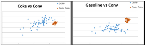
FIG. 3. Example of comparison of products yield (coke and gasoline) in a commercial high severity FCCUb (com. Data) and catalytic CTC a pilot plant (DDPP) units.
Expected differences were observed, mainly due to the pilot’s isothermal operation vs. the adiabatic nature of the commercial unit. To refine the comparison, a narrower and more representative dataset was generated using an in-house kinetic model. A corrective factors methodology was then applied to align yield vectors between the pilot and the commercial high-severity FCCUb.
The results demonstrated that the catalytic CTCa converter can achieve optimal yields, producing approximately 40 wt% total light olefins from processing AXL crude oil. When integrated with other downstream processes, a catalytic CTCa-based complex can produce more than 70 wt% combined olefins and aromatics.
Heat balanced yield model. A heat-balanced yield model was developed for the catalytic CTCa converter’s reaction and regeneration sections. This model predicts product yields, including coke formation and overall conversion, and determines the corresponding reactor and regenerator operating conditions required to achieve overall process heat balance. It helps identify whether there is a deficit or surplus of coke for combustion in the regenerator and whether a catalyst cooler is needed to maintain the desired reactor temperatures.
Using feed properties and operating parameters for both the light fraction and heavy fraction reactors, product yields are first estimated through kinetic correlations derived from pilot plant data. The resulting coke yield and conversion values are then used in the heat balance calculations to assess any additional coke requirements, such as those provided through torch oil.
This heat-balanced yield model enables accurate prediction of product yields and torch oil demand across an optimized yet practical range of operating conditions for commercial-scale catalytic CTCa applications.
Hydrodynamics. Another major milestone in the accelerated development of the catalytic CTC technologya was the completion of a comprehensive hydrodynamic study that combined large-scale CF modeling with CFD simulations. The study utilized operational and geometric data from the commercial high-severity FFCUb to support CFD validation. While CF studies do not capture thermal or cracking effects, they provide valuable information for optimizing reactor geometry, catalyst and gas distribution, and overall hydrodynamic performance.
Data from the CF experiments were used to enhance understanding of catalyst-feed mixing behavior in the catalytic CTCa reactor and to validate CFD model predictions. The chosen operating conditions were representative of the targeted commercial-scale catalytic CTCa DFR, increasing confidence that the proposed DFR design would meet performance objectives. These findings established improved internal design guidelines for the catalytic CTCa converter and provided critical input for calibrating CFD models, specifically by identifying suitable drag laws for the dense flow regime typical of catalytic CTCa operation.
The CF model, equivalent to a 2,000-bpd capacity, featured a single DFR capable of operating across a wide range of catalyst flux rates, including those projected for commercial light and heavy fraction DFRs. Prior to finalizing the reactor size for the CF study, CFD simulations (conducted with Barracuda VR software) were performed to evaluate the effect of reactor diameter on axial and radial gas-solid mixing patterns.
The CF DFR incorporated a multilayer packing system at its top to ensure uniform catalyst distribution, along with an air feed injection section designed to simulate feed injectors and steam nozzles. The unit was designed, constructed and operated at Tsinghua University in China (FIG. 4).

FIG. 4. Schematic diagram of the CF system.
To ensure continuous catalyst circulation within the cold flow DFR unit, several supporting components were incorporated, including a large-capacity catalyst hopper, a quick separator and a lift riser. Additional elements such as transport pipes, cyclones and storage tanks were also integrated to achieve effective separation between the flowing air and catalyst.
Hydrodynamic data for air and catalyst flow in the DFR feed mixing zone and subsequent reactor sections were collected along both axial and radial directions using pressure taps, optical probes, hydrogen (H2) gas tracing and solid accumulation measurement tanks. Catalyst volume fraction and velocity profiles along the feed nozzle direction were determined and compared to CFD model predictions under identical conditions. The results showed strong agreement between experimental and simulated data for catalyst distribution and velocity profiles.
This validation confirmed the reliability of the developed CFD models for both the CF setup and the commercial-scale high-severity FCCb configuration, thereby reducing the need for further experimental studies and enabling more in-depth analysis of operating conditions and DFR design effects.
CFD simulations to support key features of technology design. The commercial-scale mechanical configuration of the catalytic CTCa converter was designed based on experimental findings and simulation data obtained from earlier development stages (FIG. 5). For a 120,000-bpd unit processing crude oil such as AXL with a 350°C cut, the setup would require three DFRs sharing a single stripper for cracking the light fraction, and two additional DFRs sharing another stripper for cracking the heavy fraction.

FIG. 5. Catalytic CTC technologya features.
To maintain heat balance, torch oil may be continuously injected at the base of the lift line regenerator in certain cases, ensuring uniform hydrocarbon distribution across catalyst particles. Additionally, a catalyst cooler can be installed on one of the withdrawal wells (WDWs) to adjust the outlet temperature from a DFR to the desired operating level.
CFD simulations using Barracuda software were conducted to support and validate key design aspects of the catalytic CTC technologya. These included:
- The combined transfer of light fraction and heavy fraction spent catalysts—with differing coke contents—through a single lift line to the regenerator
- The potential injection of torch oil at the bottom of the lift line regenerator for heat balance control
- The integration of a catalyst cooler on one withdrawal well to fine-tune DFR outlet temperatures as required (FIG. 6).

FIG. 6. Illustration of computational fluid dynamics results for the key section of the catalytic CTC technologya.
Since the spent catalyst from the light and heavy fraction DFRs contains varying levels of carbon, thorough mixing is essential before entering the regenerator to prevent localized overheating that could damage the catalyst. CFD simulations of the lift line, calibrated using models based on the high-severity FCCUb, confirmed uniform mixing and homogeneous distribution of catalyst particles prior to the regenerator. Similarly, CFD analysis of torch oil injection demonstrated even dispersion across the catalyst particles, ensuring effective heat distribution and avoiding hot spots within the regenerator.
Additional CFD studies were completed on the entire WDW system, including the catalyst cooler return distributor and catalyst outlet lines to the DFRs. Results showed consistent flowrates and uniform catalyst temperatures across all outlets. Monitoring of particle residence time and temperature distribution revealed no significant maldistribution, confirming stable and well-balanced catalyst circulation between the WDW and the DFRs.
Catalytic CTC technologya converter risk assessment. A comprehensive risk assessment was performed on the catalytic CTC technologya converter design to identify potential design risks and establish corresponding mitigation plans. With these mitigation measures in place, the catalytic CTC technologya converter design has been effectively de-risked and is expected to meet its targeted performance and reliability objectives.
Basic engineering package (BEP). A conceptual BEP was developed, incorporating comprehensive data that fulfills all requirements for making the technology commercially ready, along with additional engineering design details that are applicable universally and not restricted to a specific site.
Catalytic CTC technologya converter-based complex. The integration of the catalytic CTC technologya converter into a broader catalytic CTC complex represents a strategic opportunity to maximize chemical yields directly from crude oil. Rather than deploying the CTCa technology as a standalone unit, recent studies have explored its combination with complementary petrochemical technologies to form a fully integrated greenfield complex. This approach enables refiners to design a configuration that is both flexible and optimized for market-driven product slates, while maintaining high conversion efficiency and economic viability.
The concept builds on the strengths of catalytic CTCa technology as a direct crude conversion technology, capable of processing both light and heavy fractions in dedicated downflow reactors. These reactors produce intermediate streams rich in olefins and aromatics molecules, which can be upgraded in downstream units such as hydroprocessing units, a mixed-feed steam cracker (MFSC) and an aromatics complex. By integrating these technologies into a unified complex, licensors can tailor the configuration to specific strategic customer objectives, whether maximizing light olefins, enhancing BTX recovery or achieving a balanced petrochemical output.
To evaluate the performance and viability of such an integrated complex, a detailed configuration study was conducted based on a 5-MMtpy facility processing Arabian Light crude. Two strategic pathways were modeled:
- Max olefins configuration: Focused on ethylene and propylene production, this setup routes C2 and C3 streams from the catalytic CTCa unit to shared recovery sections with the steam cracker (FIG. 7). C4 hydrocarbons are fully hydrogenated and isomerized to n-butane and recycled to the steam cracker, while full-range naphtha is hydrotreated and fed into the MFSC. Light cycle oil (LCO) is upgraded in a hydrocracker, producing additional naphtha for steam cracking. Slurry oil is treated and blended into low-sulfur fuel oil (LSFO), ensuring minimal waste and high conversion efficiency.
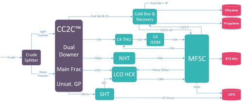
FIG. 7. Max olefins configuration.
- Max aromatics configuration: Designed to enhance BTX recovery, this pathway leverages the aromatic-rich nature of naphtha and LCO. Saturated heavy naphtha cuts are routed to catalytic reforming units, while paraxylene and benzene are recovered in a dedicated aromatics complex (FIG. 8). The configuration offers a more balanced output of olefins and aromatics, suitable for regions with diversified petrochemical demand.
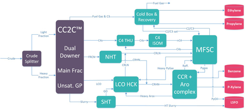
FIG. 8. Max aromatics configuration.
The results of the study confirmed the technical robustness of both configurations. Conversion rates exceeded 70 wt% of crude feed transformed into petrochemicals, with each pathway delivering strong performance in its respective product focus. The max olefins configuration achieved superior yields of ethylene and propylene, while the max aromatics setup delivered high paraxylene output. These outcomes validate the efficiency and adaptability of the catalytic CTCa-based complex.
From an economic perspective, the integrated complex demonstrated compelling returns. While conventional refining schemes often struggle to deliver attractive profitability, both catalytic CTCa-based configurations significantly outperform typical benchmarks, each achieving internal rates of return well above 15%.
These figures reflect not only the high chemical yields but also the streamlined nature of the complex. The number of units is reduced compared to traditional refining setups, and all technologies involved are either commercially proven or derived from established platforms. The catalytic CTCa itself builds on the success of the high-severity FCCb technology, ensuring low implementation risk and faster deployment.
While the greenfield concept already shows strong technical and economic performance, its potential is further amplified when integrated into an existing refining or petrochemical site. In a brownfield context, additional synergies can be leveraged to enhance efficiency and reduce capital intensity. For example, low-value or underutilized streams from the existing refinery—such as fuel oil or heavy aromatics—can be routed to the new complex for upgrading into petrochemical products. Conversely, intermediate streams from the catalytic CTCa complex can be processed in existing units with spare capacity, such as hydrocrackers, reformers or steam crackers.
Beyond stream integration, brownfield deployment allows for shared use of site services, utilities, logistics and storage infrastructure. This reduces duplication, lowers operating costs and improves energy efficiency. The modular nature of the catalytic CTCa complex also enables phased implementation, allowing operators to scale up chemical production incrementally in response to market demand.
In summary, the integration of the catalytic CTCa technology into a broader CTC complex—whether greenfield or brownfield—offers a highly flexible, economically attractive and environmentally responsible pathway for future petrochemical development. The configurations studied demonstrate how refiners can achieve high conversion rates, strong profitability and strategic agility by combining catalytic CTCa with complementary technologies in a unified, synergistic framework.
Takeaways. The catalytic CTCa technology has been effectively de-risked through collaboration with industry-leading technical partners, integrating insights from the commercial high-severity FCCUb and extensive pilot testing, CF experimentation and CFD simulations. Optimal process yields were achieved, producing approximately 40 wt% total light olefins directly from crude oil under commercial-scale conditions. A robust DFR design was developed, building on the high-severity FCCUb technology platform, supported by large-scale CF studies and validated CFD modeling. A conceptual BEP covering the converter’s mechanical configuration, pressure and material balances, and cost estimation has been completed, establishing a solid foundation for subsequent detailed engineering work.
Beyond the converter itself, the integration of the catalytic CTCa technology into broader configuration scenarios has demonstrated its strategic value. The greenfield complex study confirmed that high petrochemical yields and strong economic performance can be achieved through smart combinations of catalytic CTCa technology with downstream technologies. Moreover, the concept becomes even more compelling when deployed in brownfield environments, where existing infrastructure and spare capacities can be leveraged to further enhance efficiency and reduce costs. These findings position the high-severity FCCUb not only as a breakthrough technology, but as a central building block for future-ready CTC complexes.
NOTES
a Axens’ Catalytic Crude to Chemicals technology (CC2C™)
b Technip Energies’ HS-FCC™
LITERATURE CITED
1 Zhang, C., Q. Xu, A. Bourane, M. Ghrami and I. Abba, “Stability analysis of gas-solid distribution through nonidentical parallel paths,” Industrial & Engineering Chemistry Research, Vol. 59, Iss. 14, pp. 6,707–6,715, 2020.

Comments